Electronic bottle sanitizer for home brew
24 March 2013
A typical home brew beer recipe makes a 21 – 23 L batch. If you’re not kegging, this means 70 empties or 30 swappas. Either way, that’s a lot of cleaning, sanitizing, priming, filling and capping.
After several batches, I got sick of the process. Something had to be done about this cumbersome ordeal, especially the bottle sanitizing. Here, I would typically fill a bottle with ~100ml sanitizer, cover with my thumb, shake, then carefully transfer to the next. Quite a tiring process and also not good for my thumb.
The better option was a Vinator, a manual pump-action recirculating sanitizer, but pricing was prohibitive. Besides this, the manual pump action wasn’t enough of an improvement to convince me to purchase. What was I to do?
Soln.
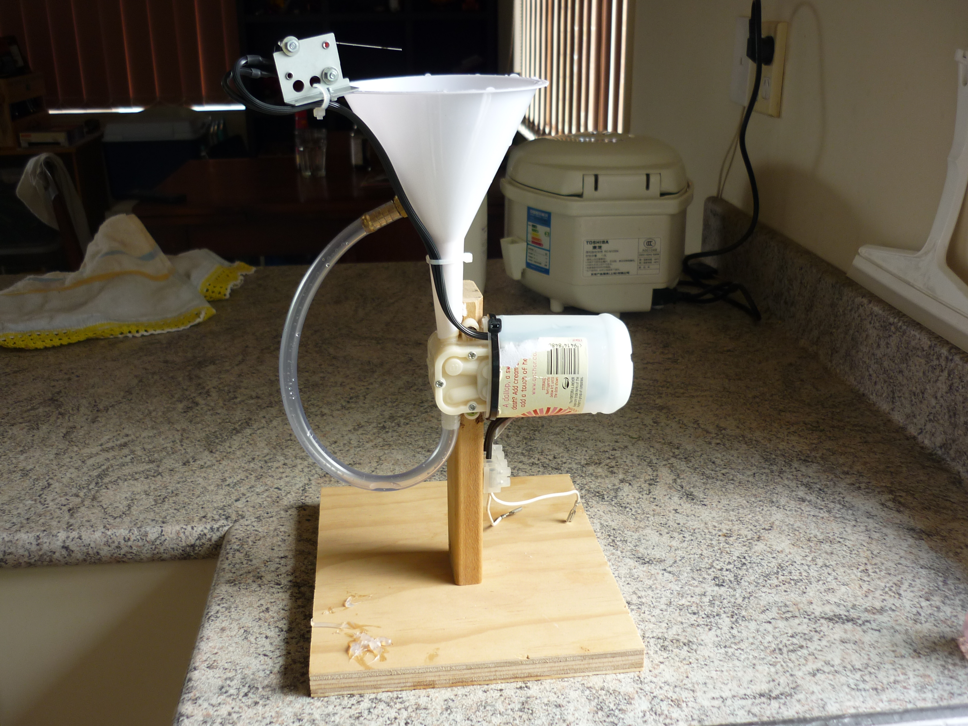
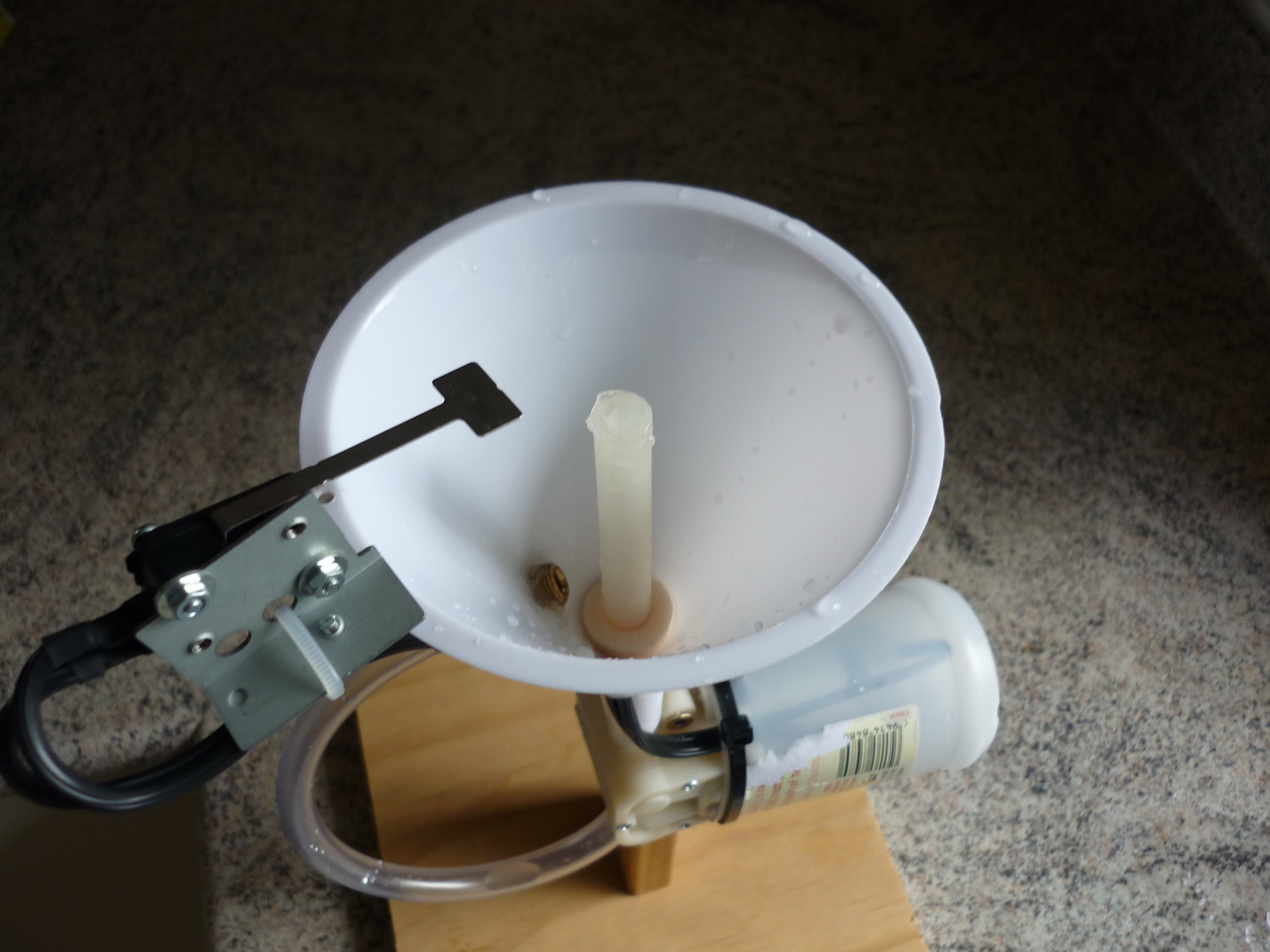
No more dilemma. This is my (prototype) electronic pump-powered recirculating sanitizer. It uses a high pressure diaphragm pump to force sanitizer through several pinholes in a silicone rubber nozzle. A microswitch, by contact with a bottle, activates the motor (I tried a light curtain set-up with inconsistent results so went for the boring option instead.)
Well anyway, it works:
It can even sanitize my ceiling…
Field trial will commence with my next batch 😉
The One Day Remote
5 June 2012
In an effort to inhibit sound from a wall-mounted television from propagating through to the adjacent bedroom, I pieced together an amplifier to drive two external speakers down the back of the living room.
With some scrounging around, I found an old RC volume control kitset from an issue of Silicon Chip magazine, so in this went. I also found various old remotes, but alas, not one using the required RC-5 protocol (not to be confused with the similarly named cipher). What was I to do? …hunt around for weeks for such a remote? Perhaps try my luck on an unbranded “universal” jobby? No. Well, actually yes to the latter, but unfortunately Murphy had his way. Go figure.
Soln: Make a crude RC-5 remote to train a professionally designed programmable remote.
With a few hours to spare, some stripboard, and some salvaged parts, I came up with the One Day Remote:

..and it worked first go. Take that, Murphy!
This baby has the grunt of a 32 bit ARM clocked at 48 MHz (LPC1111, ext. 12 MHz crystal). Overkill for a standalone remote, but certainly fit for training something more suitable.
At the risk of getting too technical, I’ve simply linked the self-explanatory source code. You’ll need cr_startup_lpc11.c (by Code Red) and CMSIS 1.3 libs, both of which are supplied with the LPCXpresso IDE. The LPCXpresso dev. kit should work fine and only costs a few $.
Now to buy a remote 🙂
Snubber
4 May 2012
A comment was made about a capacitor seen across the inertia wheel motor in this post. Just so you know, that was for test purposes only; don’t go putting 100 nF across your 20 kHz MOS driver outputs!
The VHNH2SP30 driver can operate at a supply voltage of up to 16 V, though the maximum rating is 41 V. If 16 V is exceeded, the device shuts down which causes erratic behavior if ignored.
The Mabuchi RS-555PH motor I use has an armature resistance of about 1 R, so with an 11.1 V LiPo @ 0 RPM, that causes what would seem like a relatively large current for such a small ‘bot, but it’s needed for the torque. Anyhow, when the motor commutates, especially at low speeds, all the resulting stored energy gets dumped across an unloaded H-Bridge causing some large voltage transients that shut down the driver. There isn’t much voltage margin to play with so my solution was plonk a 15V TVS across the terminals.
An RC snubber compliments the TVS’s clamping ability by reducing the dV/dt. The resistor was selected to produce < 16V with maximum motor current. The capacitor was chosen quite conservatively to limit power wastage in the resistor to 1W @ 20 kHz. It should help to reduce noise that might interfere with the Bluetooth transceiver but I’ve not verified this.

Awesome bicycling robot
23 April 2012
I got this video link from the Robonz mailing list and thought it was blogworthy:
I think it beats Murata Boy!
*edit. Better video here:
remote
19 March 2012
While I wait on a new battery and optical sensors, it’s time to work on a remote controller:

Details:
- Bluetooth (old buggy v1.1 CSR chipset),
- LED to indicate power (flashing) and successful pairing with slave module (on 100%),
- Joystick salvaged from some game console controller,
- Power switch,
- Oversized die-cast box 😉
New wheel
29 February 2012
My $2 scooter wheel arrived today. It’s a MGP Aero 100mm wheel, with a beautiful part-machined hub. After 20 minutes in the lathe grinding out the flat spots and giving it a round (side-to-side) profile, it’s as good as new!

Being rigid, I expect to see in improvement in lateral loop stability when I fit this to my unicycle robot. It’s also more circular than the existing el cheapo pneumatic tire, so there might be some improvement in the forward loop stability as well – although it still has backlash and a lack of tuning to contend with 🙂
IWP – Matlab/Simulink
19 February 2012
I had a request for an IWP Matlab/Simulink model, so here goes.
What I’m posting is dated October 2008, and was what I wrote to tune my IWP. I don’t remember much about it, but it looks reasonably self-explanatory.
Note that I’ve updated the Simulink model to Matlab R2011b and it appears to work. To run the simulation, first run the Matlab script.
The model should look like this:

To fill in the gaps:
- “x1dot” through to “x3dot” represents the second derivatives of pendulum angle, pendulum rate, and wheel rate, i.e. the non-linear system model.
- Feedback gain “-k” is the linear controller.
- The only transfer function block is the motor delay model. The addition of this is a bit confusing as I should have included it in the system model above. Also, the controller is not designed with this taken into account. It can be replaced with a straight-through connection since the inertia of the wheel and resulting time response completely swamps the inertia of the motor and it’s unloaded time response. I left it in for the fiddle factor (for fiddling with ;-)).
- The functions at the bottom are the PMDC motor torque to terminal voltage equation. I included this to get an idea of what kind of signal I would need to drive the real system. You’ll notice in the following graph [below] that there is a directional offset added to overcome friction preventing a small terminal voltage from turning the wheel (essentially a dead-space in the zero-velocity region). This dead-space isn’t modeled, but in real life I found implementing the bias helped the controller to keep the pendulum “on its toes”, though the effect would probably not be noticed with a larger inertial load. It also wastes power.
The output of the simulation should look something like this:

DL Links:
Hope this is of use 🙂

